Please have a look, the following is the DIY procedure of a simple pick and place machine, such as the various components, bearings, motors, drive systems, frame materials, etc for the machine building.
- Main Frame assembly
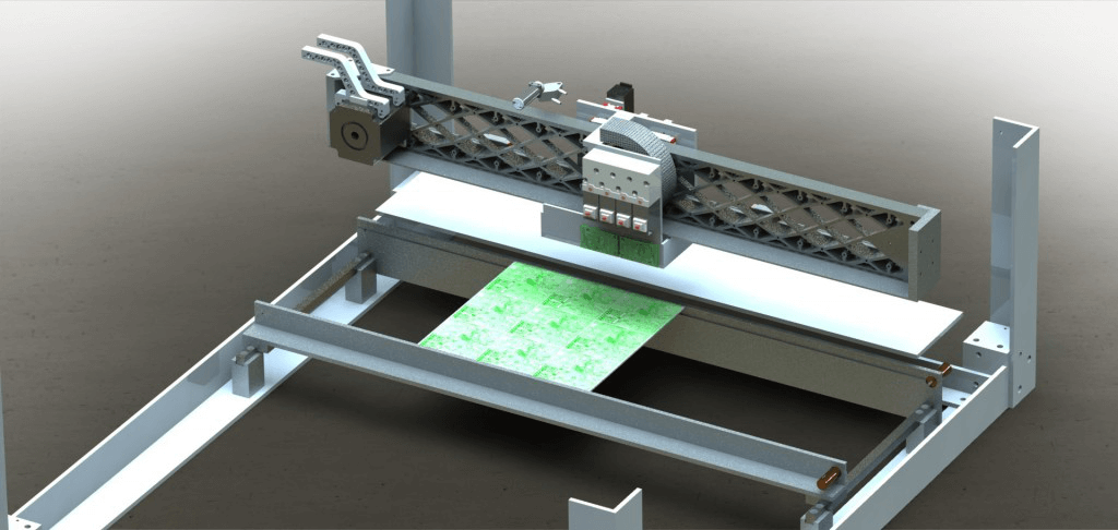
For the frame, you can try aluminum extrusion as this would be easy to assemble, light, and ridged, and allow you to easily adjust the positions of different parts by sliding them along the rails.
The main framework can have 60mm x 20mm extrusion with 20mm x 20mm on the component picker rails and 40mm x 20mm on the component feeder assembly.

Main machine frame
- Bearings and Drive systems
In order to make sure accuracy when placing components on an automated system, it is better to use some good quality linear side bearings on the X and Y-axis.
For instance, you can select the vertical slide bearings for the picker heads and component feeder head, which has the advantage that they were compact, precise, and had built-in end stops.
So the heads wouldn’t accidentally fall off if you make something wrong in the software.

Bearing and drive system
- Placement Heads and Vacuum Control
If you would like to build the pick and place machine with fast speed and precise accuracy, you should choose a high pitch lead screw with a Delrin nut connected directly to a Nema 8 stepper motor.
You can use two picker assemblies, which can make you use two different nozzles of various sizes. At the same time, you don’t have to change nozzles halfway through a building process.
Furthermore, for rotating the components, you can use a hollow shaft NEMA 8 motor with the nozzle fitted on one end and a Delrin cap fitted over the top end with the vacuum hose attached, which would allow free rotation of the nozzle without leaking air into the vacuum hose.
A coupling system was necessary through using a pair of brass pins held onto the motor shaft with a rubber o-ring. This will help you quickly pull out a nozzle and replace it with a different size.
A small amount of spring can be added to its nozzle assembly. So, if it pushes down too far with a component, it will not damage the component or lose track of the picker height.
- Component tape feeders and actuators
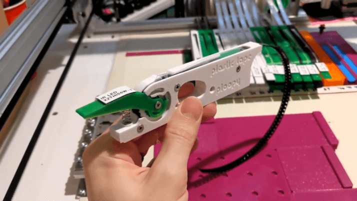
With regard to the feeders to hold the components, you may try to adapt the stepper motor on the vertical slide and exchange it with a pneumatic ram that is activated by the solenoid on the placement head assembly.
What is more, it is better to buy a noiseless stepper for the reason that the workshop compressors at cheaper prices will have a lot of noise and would annoy your neighbors.
- Tube fed chip feeder system
The feeder system for tube supplied chips is a vibration feeder, which can shake the chips down the tubes as well as putting into a picker location at the base.

Feeder system
The base of the assembly was machined from a section of 20mm Delrin sheet and the separate inserts for each chip size from a 4mm aluminum sheet.
Over this, a clamping plate was fitted and this holds a vibration motor from an X box game controller.
In the backside of the feeder, here is a threaded bar that can clamp each side of the component tubes by the nuts.
Controlled by the PC software, the motor can feed a component to the right location to be picked at around 750ms every time.
- Vision system
The vision system compromises of two USB cameras, a base camera with a large LED array, which will use Open CV to detect the component held above and determine if the position and rotation are correct,
besides, which applies any changes necessary and the head camera will work to find the location of the PCB and set the offsets. It will also work well for manual placement.
The basic LED light sources have 140 red LED beams that are controlled by a customized driver and dimmer board.
Microsoft X-box vision camera is the base of the camera module, and the small head camera with 8mm wide view can be bought from eBay, which with 10m lead and was sold as an endoscope camera.
- Control boards and interfaces
For controlling the pick and place machine, you can use a combination of commercial drivers combined with parts, such as a controller, switch panel, and a ribbon cable, to connect the breakout board with another board that contains the power supplies and relays to active different parts of the machine.
The ribbon cable provides power to the smooth stepper board and communication between the smooth stepper and the relays.
- Software
You can try to use a fully-featured Windows application to control the pick and place machine and include camera vision using Open CV.
Please make sure that when loading the board’s component list and also board settings including offsets, feeding rates, and thickness of the PCB board, which is used to calculate the correct placement height.
What is more, you should also have the vision system and manual control system to complete to interface it with a Leap motion controller.
Keywords:
LED Lamp Machine Assembly Line, LED Bulb Assembly Machine Line, SMT AutomatIC Printer, Kik Reflow Oven Profiler, Acrab 450 Wave Soldering Machine, SMT Fuji Machine, PICk And Place SMT, SMD PICk And Place Machine Fully AutomatIC, PanasonIC SMT Machin, SMT Machine Low Production, Desktop PICk And Place, MICro Robot PICk And Place, , PCBA Cleaning Machine, PCB Cleaning Machine, PCB Cleaner, Stencil Cleaning Machine, Stencil Cleaner, Machine Clean LED PCB, RobotIC Arm Screw, Inline Screw Robot, Desktop RobotIC Screw Fastening, Auto Fastening Auto-Screwdriving Machine AutomatIC Fixing Screw Robot